KIRA rolling gate control, receiver
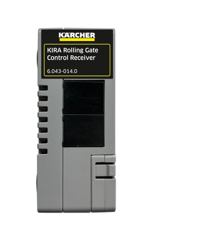
59802750 (12/24)
59802750 (12/24)
 Read these installation instructions and the safety instructions supplied with the device before carrying out the conversion. Proceed accordingly.
Keep these installation instructions and safety instructions for future reference or for future owners.
The conversion kit consists of:
Component | Description | Quantity [pieces] |
|---|---|---|
6.043-019.0 | Receiver | 1 |
6.043-018.0 | Receiver label | 1 |
5.980-275.0 | BTA rolling gate control, receiver | 1 |
5.980-277.0 | Safety instructions for rolling gate control, receiver | 1 |
The label is pre-attached on delivery.
The rolling gate control extension kit may only be used on rolling gates with force limiting devices or electro-sensitive protective equipment, e.g. gates of the type C (or D/E) in accordance with DIN EN 12453.
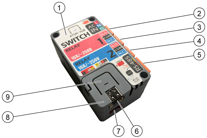
The rolling gate control extension kit for 2 relays consists of 2 modules:
KIRA Rolling Gate Control, transmitter
KIRA Rolling Gate Control, receiver module
The transmitter and receiver module must be installed by the user.
 The packing materials can be recycled. Please dispose of packaging in accordance with the environmental regulations.
 Electrical and electronic devices contain valuable, recyclable materials and often components such as batteries, rechargeable batteries or oil, which - if handled or disposed of incorrectly - can pose a potential danger to human health and the environment. However, these components are required for the correct operation of the device. Devices marked by this symbol are not allowed to be disposed of together with the household rubbish.
Current information on content materials can be found at: www.kaercher.de/REACH
Only use original accessories and original spare parts. They ensure that the appliance will run fault-free and safely.
Information on accessories and spare parts can be found at www.kaercher.com.
The warranty conditions issued by our relevant sales company apply in all countries. We shall remedy possible malfunctions on your appliance within the warranty period free of cost, provided that a material or manufacturing flaw is the cause. In a warranty case, please contact your dealer (with the purchase receipt) or the next authorised customer service site.
Further information can be found at: www.kaercher.com/dealersearch
Further warranty information (if available) can be found in the service area of your local Kärcher website under "Downloads".
The receiver module must be installed in a casing directly next to the rolling gate (contact protection).
The casing is not included in the scope of delivery. Follow the manufacturer's instructions for the casing during installation.
Requirement:
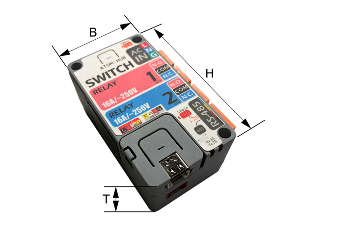
There is sufficient space for the receiver module next to the rolling gate. See chapter Technical data.
A power connection for the receiver module is available.
Install the receiver module in the casing. See operating instructions for the casing.
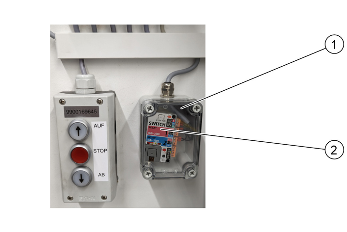
Install the casing with the receiver module directly next to the rolling gate. See operating instructions for the casing.
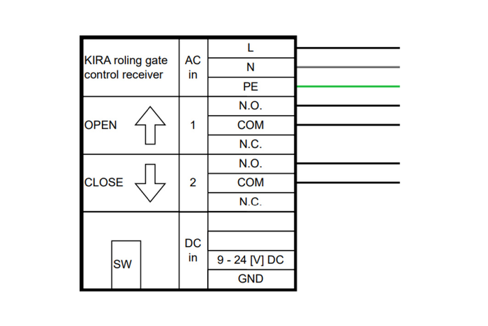
Connect the receiver module according to the wiring diagram, whereby either an AC or DC voltage supply can be connected. The connection options may vary depending on the rolling gate.
Prepare the receiver module for installation.
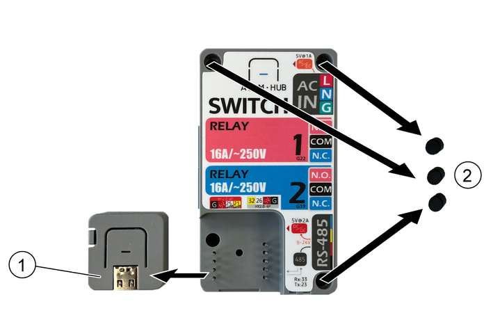
Remove the microcontroller unit.
Remove the 3 rubber stopper.
Open the casing.
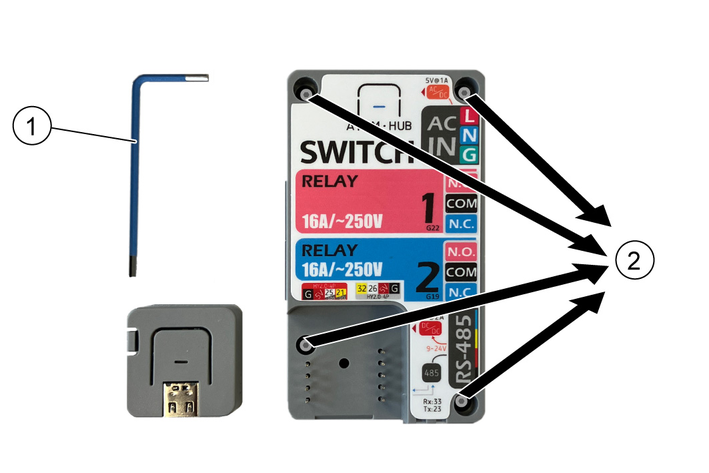
Loosen 4 screws using the blue Allen key supplied.
Remove the 4 screws.
Open the casing.
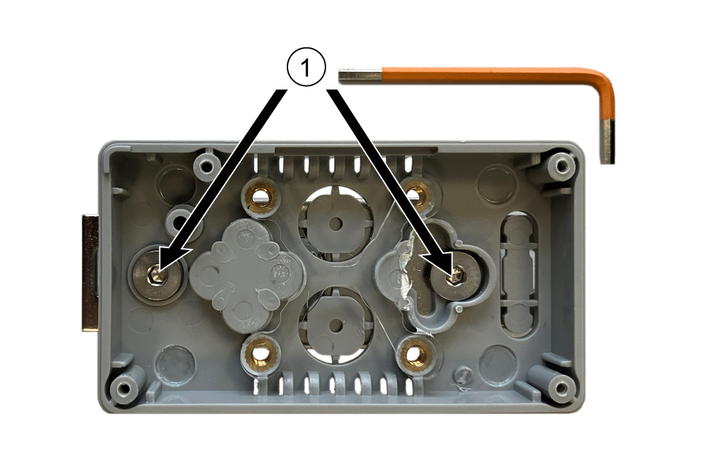
Prepare the inside of the casing for the installation of the DinRail adapter.
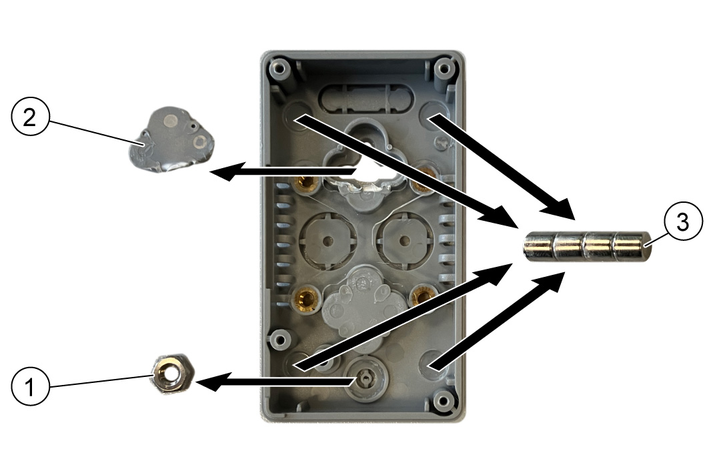
Remove the nut with plastic cover using a small screwdriver.
Remove the plastic cover using a small screwdriver.
Remove the 4 magnets (optional). They are not required for DINRrail mounting.
Fasten the DinRail adapter with 2 M4×10 screws using the orange Allen key supplied.
Close the casing.
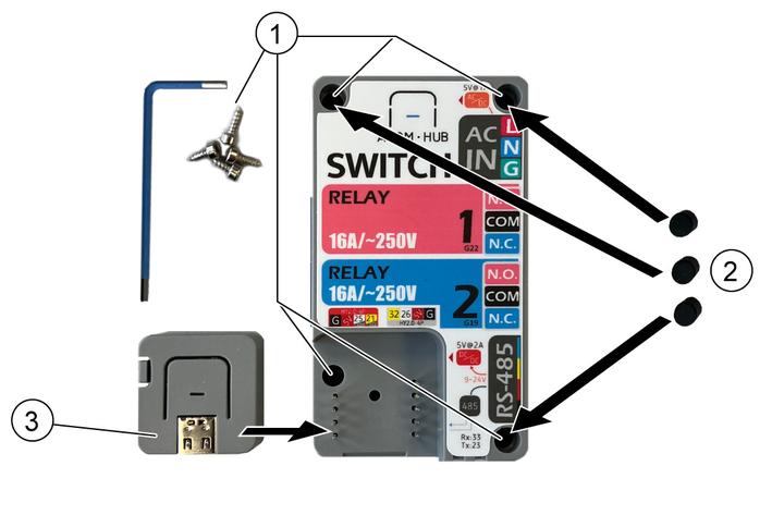
Shut the casing.
Insert 4 screws.
Tighten the 4 screws using the blue Allen key.
Insert the 3 rubber stoppers.
Insert the microcontroller unit.
Attach the receiver module to the top-hat rail in the terminal box.
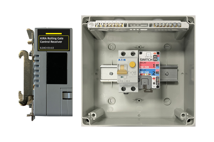
Connect the receiver module according to the wiring diagram (AC or DC).
Dismantle the microcontroller unit.
Press the switch on the microcontroller unit.
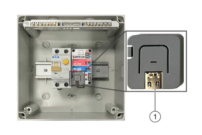
The rolling gate opens.
Electrical connection | |
Mains voltage | 220 ... 240 V |
Input voltage (DC) | 9 ... 24 V |
Input voltage (AC) | 100-240 V |
Internal relay switching voltage | 250 V |
Internal relay amperage | 16 A |
Phase | 1 ~ |
Frequency | 50-60 Hz |
Power rating | 0,6 kW |
Protection class | IPX4 |
Dimensions and weights | |
Width | 40 mm |
Depth | 30 mm |
Height | 72 mm |

0-0-0-A4-GS-AWX0674