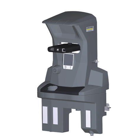
KIRA Dockingstation
00837930 (09/25)
00837930 (09/25)
 Read and adhere to these installation instructions before conversion.
Keep these installation instructions for future reference or for future owners.
The docking station supplies the Device with electricity to charge the batteries and fresh water. After docking, the waste water tank is emptied and flushed. The fresh water tank is refilled and the batteries are charged.
Observe the local waste water treatment and disposal regulations.
The water system is designed for a maximum of 1 MPa. Install a pressure limiter in the supply line if the pressure is exceeded.
Make sure that the mains cable does not come into contact with the rotating brushes, wheels or rollers of the device.
The docking station is attached to the wall with 4 screws. The diameter of the screws must be 6 mm.
When selecting the location for the docking station, please note the following:
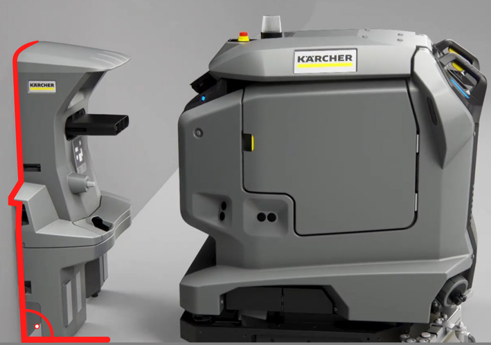
The docking station must be mounted at right angles to the floor surface.
The back of the docking station must be against the wall, the back must not be open.
The docking station should be set up on a flat surface.
The docking station should be placed on a closed surface, otherwise it will not be possible to dock without errors.
The docking station must not be set up after a ramp.
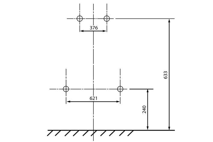
Use the enclosed fastening material or obtain fastening material according to the condition of the wall.
Place the docking station against the wall and mark holes.
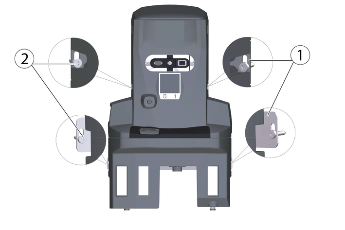
Place the docking station against the wall and screw in the screws only slightly.
Align the docking station and attach it to the wall.
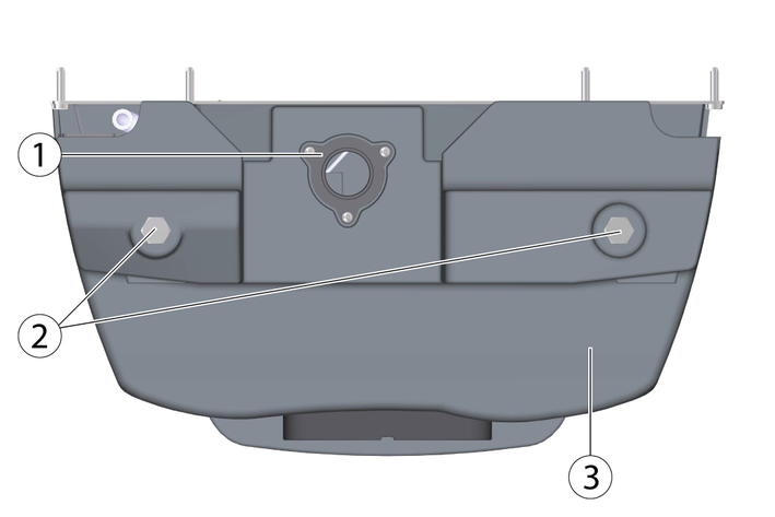
Adjust to the ground conditions with the help of the supplied washers (5 per screw foot).
4 more washers are additionally enclosed.
Tighten the screws on each side.
Connect the drain for waste water to the waste water disposal equipment. Observe local regulations for waste water treatment and disposal.
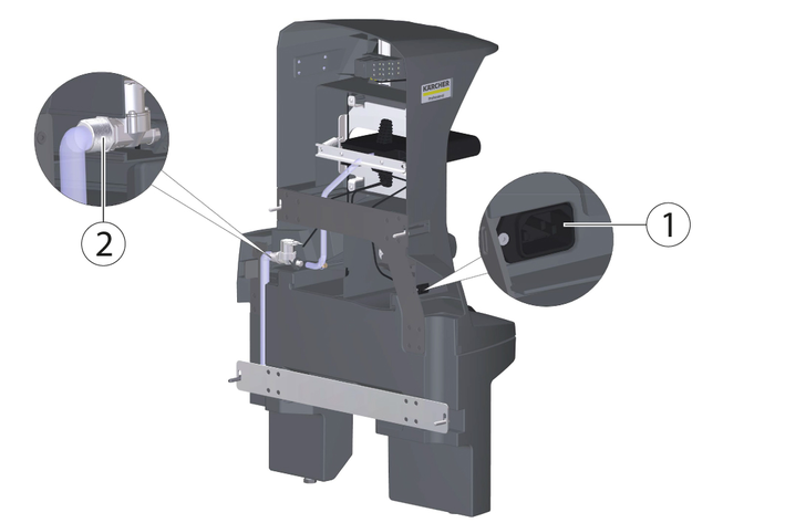
Connect the enclosed hose to the water connection.
Note the flow direction (arrow).
Connect the enclosed mains cable to the socket for non-heating apparatus on the unit.
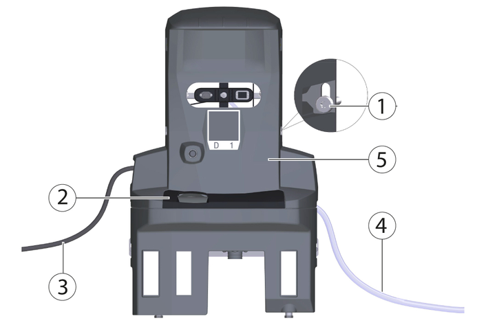
Tighten the screws on each side.
Attach the cover.
Connect the hose to the water supply. Note the maximum permissible water pressure in the chapter "Technical data". If necessary, install a pressure reducer in the supply line.
Plug the mains plug into the socket. The socket must be protected with a fault current protection switch with a country-specific permissible tripping current.
Check the function.
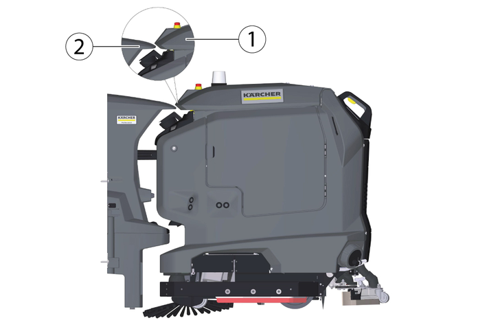
Move the Device in front of the docking station.
Check the height alignment: The tip of the wedge on the docking station must meet the slope on the lid of the dirty water tank halfway up
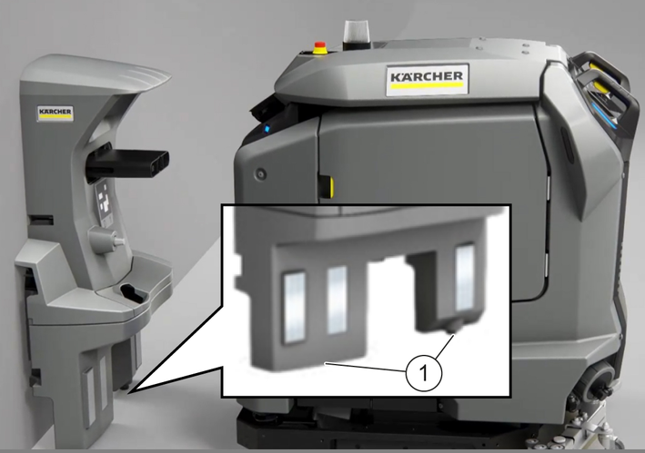
Adjust the height of the docking station with the lower adjusting screws so that the Cliff LiDAR bumper on the Device retracts under the docking station at a distance of approx. 5 mm.
Measure the difference dimension to the correct setting dimension.
Loosen the 4 screws on the docking station and remove them from the wall.
Using the washers, adjust the screw feet on the lower part by the difference dimension (one washer corresponds to 2 mm).
Place the docking station against the wall and fix it with the 4 screws.
Recheck the height alignment.
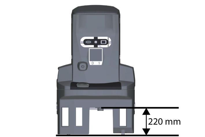
Note that the distance between the floor and the height of the drain of the waste water tank must be 220 mm.
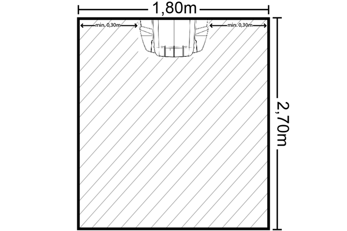
In order for the robot to dock reliably at the docking station, sufficient space must be kept free in front of the docking station. The recommended size of the zone to be kept clear can be found in the following Illustration.
To ensure that no water overflows at the docking station, a water stop valve can also be installed. The water stop valve is mounted between the tap and the Aquastop hose.
Turn off the water supply.
Set the arrow to level 8 (40 litre water flow) with the spanner provided.
The water stop valve can be set from level 1 (5 litre water flow) to level 10 (50 litre water flow) and closes automatically when more than the set amount of water has flowed through without interruption.
Attach the upper end of the water stop valve to the tap.
At the entrance of the water stop valve, an upwardly curved Water filter is installed. If the Aquastop hose has a Filter mounted, it must be replaced by a gasket to ensure the function of the Water Stop Valve.
Attach the AquaStop hose to the thread at the bottom of the water stop valve.
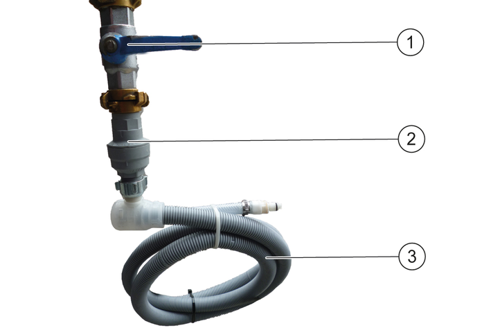
Turn the water supply back on.
Turn off the water supply.
Remove the AquaStop hose.
Turn off the water stop valve and press in the red pin.
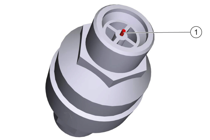
Attach the upper end of the water stop valve to the tap and press in the red pin.
Attach the AquaStop hose to the thread at the bottom of the water stop valve.
Turn the water supply back on
Device performance data | |
Number of batteries | 2 |
Nominal voltage, Li-Ion | 25,6 V |
Battery capacity, Li-Ion | 160 Ah (5 h) |
Mean power input | 1600 W |
Driving motor power | 2x280 W |
Suction Turbine Power | 630 W |
Brush Drive Power | 600 W |
Running time with full battery | 3,5 h |
Protection type | IPX3 |
Internal charger | |
Rated voltage | 100...240 V |
Current consumption | <7,5 A |
Frequency | 50-60 Hz |
Power | 760 W |
Charging current | 30 A |
Battery charging time | 8 h |
Waste water pipe | |
Nominal width of drain | 50 mm |
Minimum slope of waste water pipe | 1-3 ° |
Lifting unit requirement | |
Pumping capacity of the wastewater lifting station | ≥ 6,5 m3/h |
Minimum slope of waste water pipe | 1-3 ° |
Dimensions and weights | |
Weight | 15,2 kg |
Length x width x height | 350 x 650 x 1050 mm |
Device performance data | |
Number of batteries | 2 |
Nominal voltage, Li-Ion | 25,6 V |
Battery capacity, Li-Ion | 160 Ah (5 h) |
Mean power input | 1600 W |
Driving motor power | 2x280 W |
Suction Turbine Power | 630 W |
Brush Drive Power | 600 W |
Running time with full battery | 3,5 h |
Protection type | IPX3 |
Internal charger | |
Rated voltage | 100...240 V |
Current consumption | 9,9-4,7 A |
Frequency | 50-60 Hz |
Power | 960 W |
Charging current | 40 A |
Battery charging time | 5,25 h |
Waste water pipe | |
Nominal width of drain | 50 mm |
Minimum slope of waste water pipe | 1-3 ° |
Lifting unit requirement | |
Pumping capacity of the wastewater lifting station | ≥ 6,5 m3/h |
Minimum slope of waste water pipe | 1-3 ° |
Dimensions and weights | |
Weight | 15,2 kg |
Length x width x height | 350 x 650 x 1050 mm |
Inadvertently starting up of the unit, touching live components
Risk of injury, electric shock
Before doing any work, disconnect the Device from the docking station or pull the Mains plug.Danger from electric shock.
Before working on the docking station, unplug the Mains plug from the power outlet.Remove the cover.
Check the float switch and float, clean if necessary.
Clean the waste water collection tray and rinse it with water.
Attach the cover.
Den Position code clean with a damp cloth.
Check the male docking port for ease of movement.
For suitable use of the docking station, an open space in front of the docking station 2x2 m2 to provide for
We hereby declare that the machine described below complies with the relevant basic safety and health requirements in the EU Directives, both in its basic design and construction as well as in the version placed in circulation by us. This declaration is invalidated by any changes made to the machine that are not approved by us.
Product: Kira Docking Station
Type: 2.042-xxx
Currently applicable EU Directives2006/42/EC (+2009/127/EC)
2014/30/EU
Harmonised standards usedEN 60335-1
EN 60335-2-72
EN IEC 63327
EN IEC 61000-6-2: 2019
EN 61000-6-3: 2007 + A1:2011
National standards used-
The signatories act on behalf of and with the authority of the company management.

Documentation supervisor:
S. Reiser
Alfred Kärcher SE & Co. KG
Alfred-Kärcher-Str. 28 - 40
71364 Winnenden (Germany)
Ph.: +49 7195 14-0
Fax: +49 7195 14-2212
Winnenden, 2021/11/01